


Updated: Jul 21, 2020
On a recent engagement we faced a difficult target with minimal external attack surface. Their website had a few flaws, but it was hosted externally with a third party. Even if we could compromise the site, it likely wouldn’t result in the internal network access we were searching for.
Thanks to Shodan, we identified a Cisco router which was externally-accessible. This is a rundown of how we leveraged this device into a full network compromise.
Disclaimer: This information would probably be nothing new for Cisco gurus or someone with a CCNA; but hopefully this post grants some security folk out there enough knowledge to turn a router compromise into internal shells in the future. As always, take extreme care when dealing with any critical network infrastructure.
The Router
Having identified a router which belonged to the target, we performed the typical enumeration we complete on every device: port scans, default password checks, SNMP checks, etc. Fortunately for us, the router had the public SNMP string set to “public”, and the private string set to the default value “private”. With access to the private string, tools such as Metasploit’s scanner/snmp/cisco_config_tftp module can be used to pull down the running configuration, or more specifically, the hashes of passwords being used on the device. The three-letter password was not particularly resilient to cracking, and in a short few minutes we were on the router with full permissions.
Great, we have access to the router – now what? We conducted an in-depth analysis of pivoting methods used for penetration testers when encountering Cisco devices. Unfortunately for us, there was very limited information out there for solving the particular constraints facing us on this engagement.
The Network
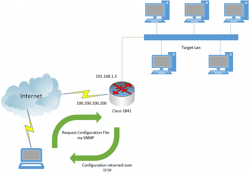
What we had done so far looked similar to the above picture. We had compromised the router via its external interface (100.200.100.200) and had pulled down its configuration file. The internal LAN was reachable via one of the interfaces with the IP address range of 192.168.1.3/24. There were further complications and interfaces, but they aren’t necessary detail for the process we went through. One of our biggest hurdles was the configuration of the internal network. Clients were being assigned an IP address via an internal router located at 192.168.1.1. This was also their default gateway for any outbound traffic. The significance of this will come into play shortly.
Failed Attempts
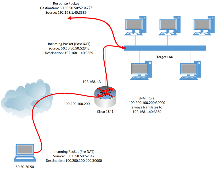
The initial naive plan was to simply port-forward a connection from the external interface through to the internal LAN, resulting in quick-and-dirty access to specific services, allowing us to obtain shells before tearing down the now-obsolete port forward. This would be a simple command for the Cisco router to perform Static Network Address Translation (SNAT). We’ll get into actual commands in the successful attempts section, but this would essentially be saying to the Cisco device, “When you receive an incoming packet on 100.200.100.200:30000, always translate this to the IP address and port 192.168.1.40:3389 and forward it on via the internal interface.” With luck, the RDP service on 192.168.1.40 would respond, the packet would be forwarded back out via 192.168.1.3, we’d enter in some stolen credentials and success! Unfortunately for us this didn’t happen.
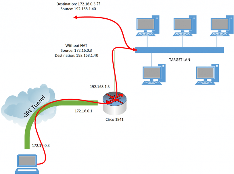
As you may have guessed from our earlier information, the problem was that the packets were not in fact coming back to 192.168.1.3, but rather, seeing that the source address (50.50.50.50) was outside of their subnet, the default gateway (192.168.1.1) was being used to try to reach our IP! To this day I don’t know why the 192.168.1.1 device couldn’t route externally. As with most security problems, these curve balls create some interesting problems that people don’t usually see. The correct solution to this routing issue would be “Reconfigure the gateway to allow routing out to our IP address”, but as we don’t control that device it’s not an option. A pictorial version of our problem is represented below.
Okay, so at the router, we’re translating the destination address to be the internal LAN, but that leaves us with an “invalid” source address for the purposes of routing. We can’t change the router to do source address translation instead of destination address translation because we’d then have no way of getting packets to the correct IP address (you can’t just set a route on your own computer saying the gateway for 192.168.1.1/24 is 100.200.100.200: the routers across the internet would not know how to honour your 192.168.1.40 destination IP). What we need is some form of double NAT; that being packets should exit the router having translated both the source and destination address. So, how to do double NAT on a Cisco 1841? The answer is not in the first 40 pages of Google results – trust me, I looked. It appears that this is possible on Cisco ASA devices, but not possible on a Cisco 1841. I attempted all manner of loopbacks / forwarding rules / NAT chains etc with no luck. I could not get the Cisco device to translate both source and destination IP addresses. If anyone knows how to do this on a Cisco 1841 I’d love to hear from you.
Our Savior – Generic Routing Encapsulation (GRE)
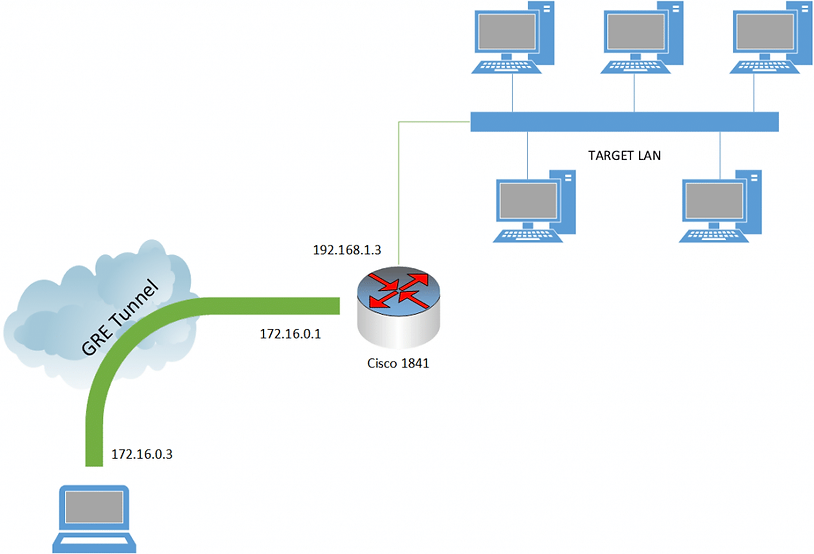
GRE is a protocol that wraps up other traffic and tunnels it through to a designated endpoint. Think of it as similar to a VPN in some ways. The key information is that this sorts out our “destination” address problem. We can set the destination to now be our target LAN subnet; an address in the 192.168.1.1/24 range; and tell the tunnel to “take care of the rest” for us in terms of getting the traffic to the target Cisco router. Anyway, enough theory, here are the commands. Here we set up a GRE tunnel with the subnet 172.16.0.0/24, assigning the Cisco device 172.16.0.1, and our device 172.16.0.3:
// On the attacking machine
modprobe ip_gre
iptunnel add mynet mode gre remote <target external ip> local <attacker external ip> ttl 255
ip addr add 172.16.0.3/24 dev mynet
ifconfig mynet up
route add -net 172.16.0.0 netmask 255.255.255.0 dev mynet

// On the Cisco device
config term
interface Tunnel0
ip address 172.16.0.1 255.255.255.0
ip mtu 1514
ip virtual-reassembly
tunnel source <Interface of WAN on the Cisco>
tunnel destination <Attacking Machine IP>
After these commands are run on both devices, you should be able to ping 172.16.0.1 from your attacking machine, and ping 172.16.0.3 from the Cisco router. We have effectively created the following picture.
NAT – New and Improved
Now we’re not quite out of the woods yet. If we examine the traffic path we still have our return address problem (pictured below). The key successful step that we’ve taken however is that we’re no longer using up our “one” NAT rule on the Cisco 1841 to get our initial destination packet into a form that is workable for us. Revisiting our original port forwarding idea, we could continue to do ad hoc SNAT rules; but we’re not going to go through all this effort to address one port at a time. There has to be a better way.
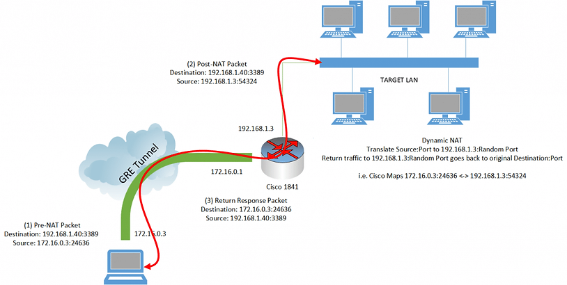
Enter – Dynamic NAT. This is more commonly-seen on your typical home setup where you have multiple devices behind your router, and then you’re “NATing” your traffic out and presenting one public IP address to the internet at large. When you consider it that way, it’s almost exactly what we want to do in this situation, however the “internet at large” is actually our target LAN. If we can perform this type of NAT, as far as the target computers are concerned, the traffic source would be coming from 192.168.1.3, and they should return the traffic to that IP address. The NAT table on the Cisco router will remember what incoming traffic produced that specific IP / port source combination, and map it back to our 172.16.0.3 address appropriately. Again this is the same thing done by your home router when receiving traffic back from the internet after you make a web request. Another key point to remember is because the source address is being translated to 192.168.1.3, this is within the subnet of the target LAN. As a result, they ignore the gateway of 192.168.1.1 which was giving us problems in the past!
Again, enough theory, what are the commands?
// On the Cisco Device
config term
interface Tunnel0
ip nat inside
interface <Internal Lan Interface>
ip nat outside
exit
config term
access-list client-list permit ip 172.16.0.0 0.0.255.255
ip nat enable
ip nat source route-map test interface <Internal LAN Interface> overload
ip nat inside source list client-list interface <Internal LAN Interface> overload
Success! With this configuration it is now possible to route traffic to the internal network from our attacking machine over a GRE tunnel. All of the 192.168.1.1/24 range is reachable from our attacking machine, and no special proxytunnels-like program is needed to access them. A final picture to show what the setup looks like. Hopefully this saves you the time it took me to figure it out!
Happy Hacking – Peleus